Bridging
Material forms a stable arch above the outlet and stops discharge.
Pneumatic silo and hopper vibrators transfer excitation into the vessel wall to support bulk-solid discharge. RVS is assessed for bridging, ratholing and wall build-up; the result depends on the material, hopper geometry and mounting. A pilot compares discharge consistency and blockage frequency before and after installation.
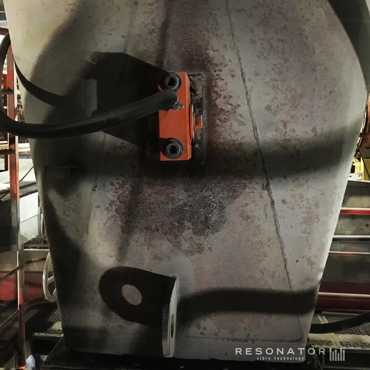
RVS units transfer resonance into the cone near the outlet, where cohesive material commonly forms arches or adheres to the wall.
A silo can contain plenty of material while the outlet receives almost none. Bridging, rat-holing and wall adhesion are shaped by material properties, moisture, vessel geometry and operating history. RESONATOR focuses vibration on the active failure zone instead of shaking the entire structure without a defined objective.
Every installation begins with the actual material, equipment and measurable production problem—not a generic device selection.
Material forms a stable arch above the outlet and stops discharge.
A narrow channel empties while product remains stationary around it.
Fine, damp or cohesive material accumulates on internal surfaces and reduces usable capacity.
Frequency, force, mounting and timing are treated as one engineered operating system. The final configuration is validated under representative conditions.
Document where flow stops, how often it occurs and what operating conditions trigger it.
Assess cone angle, outlet size, wall material, supports and structural transfer paths.
Place controlled vibration near the failure zone with a suitable mounting method.
Adjust the operating window while measuring flow continuity, residue and cycle time.
These are engineering objectives, not automatic guarantees. Performance depends on the material, structure, operating point and validation method.
Supports material movement through the outlet and reduces recurring flow stoppages.
Reduced wall build-up can help recover material that would otherwise remain in the vessel.
A defined vibration sequence can replace improvised striking or repeated operator intervention.
Choose the energy-transfer route that fits the process environment and access point.
Primary solution for external mounting on suitable cone, wall or support locations.
Specialized option where internal placement is justified and compatible with the stored material.
Engineered multi-point layouts for large vessels, difficult geometry or changing products.
Send the material, bulk density, particle size, moisture range, silo or hopper drawing, wall material, outlet size, support structure, blockage pattern and air supply.
Follow the material through your process. These application guides explain the role of excitation at the next stage and what to validate in a pilot.
Vibration can help mobilize material near a restricted outlet or wall. However, the outcome depends on cohesion, moisture, outlet geometry and mounting. Too much excitation can compact some materials, so a silo vibrator is selected through a material-specific trial.
An engineered interface transfers excitation into the wall or supporting structure near the resistance point. Position and mounting must be reviewed for the actual vessel; the application drawings are concepts, not installation instructions.