Flexible brackets
Thin plates, long cantilevers and weak supports absorb motion instead of transferring it.
Public installation principles for the RVS™ Resonance Vibrator Stationary, followed by controlled access to model-specific operating instructions.
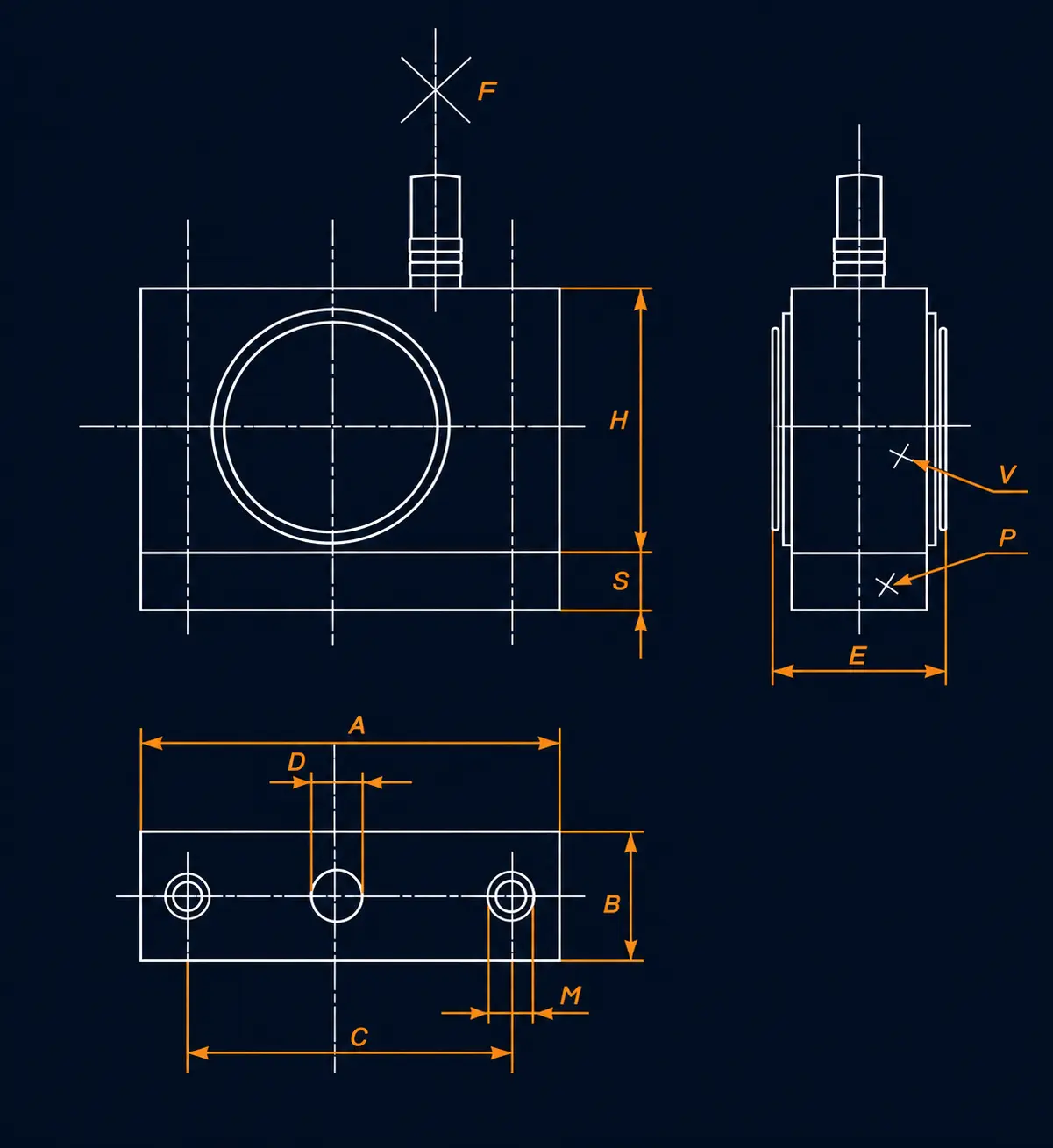
The mounting plane and support structure determine how efficiently resonance energy reaches the process. Final mounting must be confirmed for the selected RVS™ model and real operating load.
Mount the full base against a flat, structurally stiff surface connected to the process body.
Position the RVS close to the zone where vibration must enter the material or equipment.
Use the specified fasteners and verify that the support cannot flex, loosen or fatigue under repeated cycles.
Route the pneumatic line without tension, crushing, impact exposure or obstruction to service access.
These diagrams show mounting concepts, not a universal installation specification. RESONATOR must confirm the bracket, fasteners, air supply and working orientation for each application.
Incorrect orientation or a weak mechanical interface can reduce useful transfer and create unnecessary stress in the installation.
Tilted or vertical working-axis positions require engineering confirmation and should not be assumed acceptable from mounting-plane direction alone.
Thin plates, long cantilevers and weak supports absorb motion instead of transferring it.
Do not incline or rotate the active working axis without application approval.
Partial base contact or loose fasteners can create impact loading and inconsistent performance.
Do not copy air pressure, timing or cycle settings from another machine or material.
Excitation force is expressed in newtons (N); it is not power in watts. Request the current model-specific data at the intended pressure, including frequency, air consumption, mounting and load conditions. Historical RFC data and current RVS figures should not be treated as interchangeable specifications.